
Verilog code for Full Subtractor using Full Adder
1 bit Full Subtractor using 1 bit Full Adder:We defined 1st module in which we have to implement 1bit full adder and then by using its functionality, we have to implement 1-bit full Subtractor. Full adder have three input as a, b, cin and two output as sum and carry, Using the circuit diagram we have implemented 1-bit full adder using NAND gates. Now, 2nd module is defined in which we implemented the 1-bit full Subtractor using the functionality of full adder. Here, the input of full Subtractor is taken as same as that of full adder, wire x is declared which takes the value as the output of not gate and is used as input in full adder. Hence, it is implemented.
Verilog code for Full Subtractor using Full Adder:
module full_adder_1bit (sum,cout,a,b,cin);
output sum,cout;
input a,b,cin;
wire c1,c2,c3,c4,c5,c6,c7;
nand n1(c1,a,b);
nand n2(c2,c1,a);
nand n3(c3,c1,b);
nand n4(c4,c2,c3);
nand n5(c5,c4,cin);
nand n6(c6,c4,c5);
nand n7(c7,c5,cin);
nand n8(cout,c1,c5);
nand n9(sum,c7,c6);
endmodule
module full_sub1(sum,cout,a,b,cin);
output sum,cout;
input a,b,cin;
wire x;
not n1(x,b);
full_add_nand fa_n1(sum,cout,a,x,bin);
endmodule
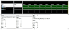
OUTPUT:


0 Comments